System description
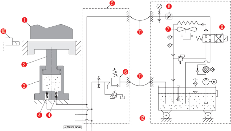
- Press Ram.
- Cylinder rod.
- Cylinders with controlled return.
- Retention valves. They intercept the flow of the hydraulic fluid into and out of the cylinders. Their presence enables to reduce the springback effect to a minimum.
- Distribution unit with pressure-reducing valve.
- Adjustable pressure-reducing valve. It regulates the outflow of hydraulic fluid during the cylinder compression phase. This pressure reducing valve ensures that the pressure, i. e. the cylinder contrasting force, remains constant.
- Air-oil exchanger. It switches on automatically and ensures that the fluid temperature remains constant.
- Compensatory flow regulator, to guarantee constant speed during the return phase.
- Two-position, two-way electrical distributor. When its coil is off,its hunts the hydraulic fluid into the air-oil exchanger; when its coil is on, it shunts the hydraulic fluid into the return circuit of the cylinders.
- Electromagnetic safety sensor: checks the correct position of the sliding tool part, which is jam-prone at the end of cycles.
- Flexible hose-pipes with quick coupling connectors to distribution unit.
- Wheeled command unit.
The positioning of the cylinders inside the tool is free and depends solely on the projects requirements; the command unit must be placed near by the press, in an open area so as not to be in the way or create a nuisance.
The use of hydraulic fluid enables an easy and optimal regulation of heat dispersal thanks to the heat exchanger which switches on automatically whenever the need arises.
This guarantees maximum reliability and operational constancy, allowing for working speeds of up to 25 cycles per minute.
Although the intrinsic compressability of the hydraulic fluid at the end of the compression phase results in a slight subsidence of rod retention, the extent of the latter is guaranteed to reach at most 0.2 mm.
![]()
This operation must take place during the installation and loading procedure of the hydraulic fluid, hence it is necessary for the cylinders to be accessible.
Once this operation has been performed, it is possible to disconnect the quick coupling connectors from the command unit and to proceed with the tool assembly.
AFTER-SALES SERVICES
To receive more informations about our products and to receive technical support please contact us.
Tel. +39 0424 539181
Fax +39 0424 898230
E-mail info@specialsprings.com